
 Yahoo Finance
 A Digital Multimeter Is a Must-Have for Any Toolbox, But It Has Its Learning Curve

"Hearst Magazines and Yahoo may earn commission or revenue on some items through the links below."
A digital multimeter is an indispensable tool for testing, diagnosing, and troubleshooting electrical circuits, components, and devices. The first digital multimeter was introduced in the late 1970s, and has proven much more accurate and reliable than the old needle-based analog meters. It’s used primarily to measure voltage (volts), current (amps), and resistance (ohms). But that’s just the beginning of what this surprisingly useful tool can do.
🔨 You love badass builds. So do we. Let’s make some cool stuff together.
Want to know how to use a multimeter properly? Here are five common ways to put your digital multimeter to good use. Note: These instructions are applicable to most multimeters. However, the exact procedures and how the screen reads out might differ slightly based on the features and functions of your particular device.
The Best Multimeters
💡Warning: Working with electricity and electrical components can be potentially dangerous. Extreme safety precautions must be followed when taking electrical measurements. Before using a digital multimeter, be sure to read and fully understand the instructions and warnings outlined in the owner’s manual.
Testing Batteries
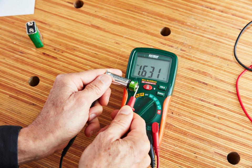
Starting with the simplest, most basic test, use the voltage mode on your meter to check battery output. First plug the meter’s black probe into the jack marked - COM (common). Insert the red probe into the jack labeled Volts or +V (next to the V, you may also see a symbol that looks like an upside down horseshoe, we’ll get to that in a minute). Most modern meters make this setup all but foolproof by also color coding the jacks. The black common probe goes into the black jack; the red probe goes in the red jack. Now turn the rotary switch (dial) to Volts DC; because batteries supply direct current (DC), not alternating current (AC).
Hold the tip of the red probe against the battery’s positive (+) outward-shaped terminal, and the black probe against the negative (-) inward-shaped terminal. The battery voltage will read out on the meter’s display screen. For example, a fully charged AA battery should have a reading of at least 1.5 volts. And you can use your multimeter to test virtually any battery ranging from AAAs to car batteries.
Note that the above-mentioned technique only tests voltage, not the battery’s ability to supply current under load. The test gives you a rough idea of whether the battery is good, shot, or needs to be charged.
Testing Electrical Outlets
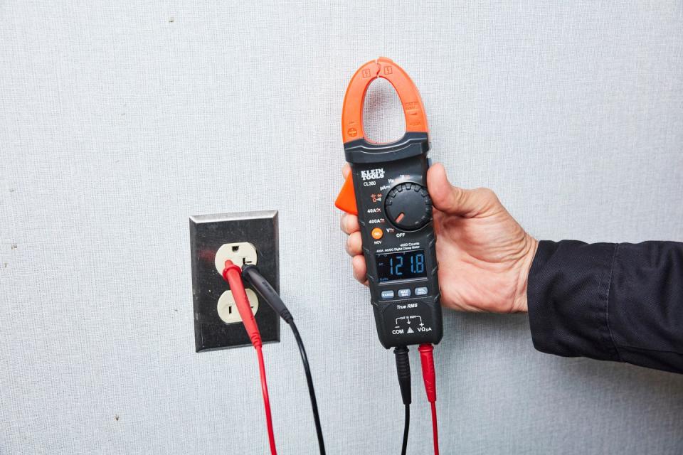
Here’s how to determine if the wall outlets in your home are delivering the correct voltage, which in most modern homes is 120 volts. Plug the black probe into the meter’s black COM jack, and the red probe into the red Volts jack. Then turn the rotary switch to Volts AC (Vac), which is also indicated by a wavy line on the dial.
Push the tip of the red probe into the shorter (hot) of the two vertical slots on the outlet. Insert the black probe into the longer slot (neutral). Check the readout on the meter’s screen. A properly functioning outlet should produce 110 to 120 volts. Next, remove the black probe from the outlet—leave the red probe in place—and insert the black probe into the small, rounded hole (ground) below the two slots. The reading should remain the same. If it doesn’t, the outlet is improperly wired or perhaps the ground is missing; call an electrician.
Testing a Wall Switch
Got a faulty ceiling light? Here’s how to determine if the problem is with its switch. First, turn off the power to the switch, remove the cover plate, and unscrew the switch from its wires. Before disconnecting the wires, label them or take a photo with your phone to ensure you reconnect them correctly. Loosen the switch terminal screws, unhook the wires from them, and remove the switch.
Rotate the meter’s dial to the Ohm setting. Set the resistance range to X1. Skip this step if your meter has auto-range (you can tell you have an auto-ranging meter if you turn the dial to the Volts AC (Vac) setting, the word "auto" appears on the screen). Plug the black probe into the COM jack and the red probe into the red V jack.
To test a single-pole switch (the simplest kind; it has two brass screws and one green screw). Flip the switch to the Off position. Now touch the meter’s probes to the brass screw terminals on the side of the switch–it doesn’t matter which probe touches which screw.
With the switch turned off, you should get a reading of O.L (you may also get other readings, such as 99999 or a symbol like this I or even this: L). This means Over Load or Over Limit; the resistance is so high that it can’t be measured. At first this doesn’t seem to make sense (you would think the meter would read zero ohms), but the meter is telling you that when no internal contacts are touching inside the switch, the resistance across the open contacts is so large that the meter can’t read it. Now flip the switch On and the meter should read less than one ohm. If it doesn’t, the switch is faulty and should be replaced.
Another simple test is to rotate the meter dial to the position for continuity. This means a continuous electrical path. The symbol for continuity on the meter’s face is a wedge shape that indicates noise waves radiating out from a point. Connect the meter across the switch contacts and flip the switch up and down. The switch is good if the meter beeps with the switch in the On position. The switch is bad if the meter doesn’t beep with the switch flipped to On.
Testing Extension Cords
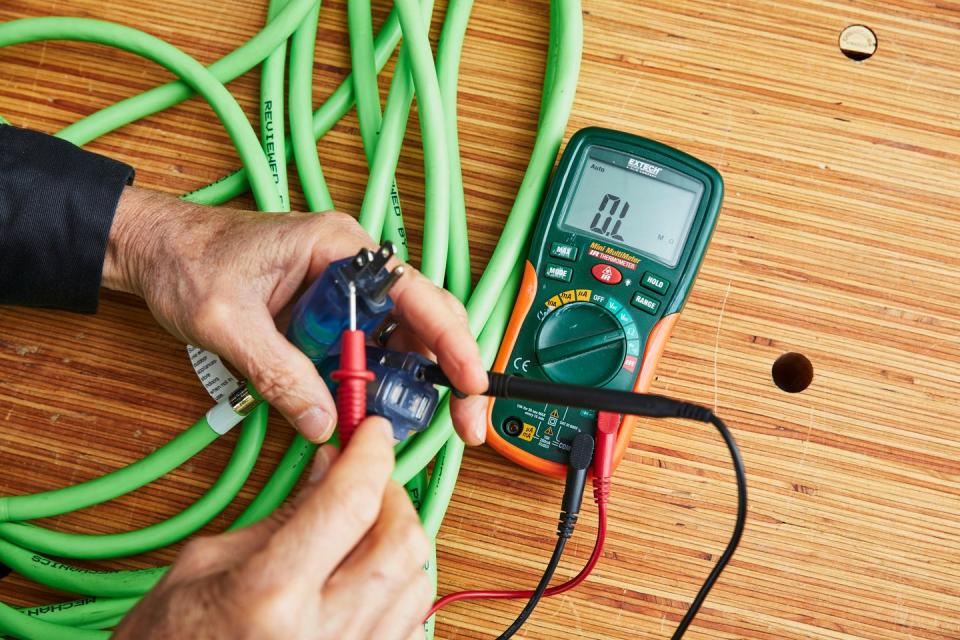
It’s smart to use your meter to occasionally test old extension cords because damaged cords can shock you or start a fire. Begin by unplugging the extension cord from the wall and turning the meter’s dial to the Ohm setting.
To test the cord’s ground, push the red probe into the small hole on the female end of the cord. Then touch the black probe to the round (ground) prong protruding from the male end. A continuous circuit measured from these two ends will have a resistance of.8 ohms or even less. Now, touch the red probe to each of the flat prongs on the male end to ensure an O.L reading. There should be an open circuit when the cord is analyzed in this fashion; there should be no contact between the wire that connects the ground pin and either of the other two wires inside the cord.
Next, insert the red probe into the short (hot) slot on the female end of the cord. Touch the black probe to the narrow flat prong on the male end. Electrical continuity through the cord will have a resistance of .8 ohms or less. Then touch the black probe to the wide flat prong and then the round prong, the meter should show no continuity and an O.L. for reading in these two positions.
Finally, take the red probe and push it into the longer (neutral) slot on the female end of the cord. Take the black probe and touch the wide flat prong. The continuity will have a resistance of .8 ohms or less. Touch the black probe to the narrow prong and then the round prong for an O.L. reading.
After confirming that the cord doesn’t have any shorts, run a voltage test. Plug the cord into an electrical outlet and rotate the meter’s dial to Volts AC. Insert the black probe into the round hole in the female end of the cord, and push the red probe into the narrow slot. You should get a reading close to 120 volts. Now move the red probe into the longer (neutral) slot to confirm a reading of about .1 millivolts (there is negligible voltage between the outlet’s ground and neutral and the cord’s ground and neutral).
Leave the red probe in the longer slot and move the black probe to the shorter slot to get a voltage reading of about 120 volts, confirming that the extension cord is in good condition.
Reading Temperatures
Besides all of its amazing electrical-testing capabilities, most modern multimeters can also take temperature readings. Simply rotate the meter’s dial to the temperature mode, then press the select button to toggle between Fahrenheit and Celsius.
Plug the thermocouple into the meter to read air temperature, or insert the temperature probe to take temperature readings of liquids, gels or to track the surface temperature of a gas dryer. You can observe the appliance’s temperature cycle without touching it with your hand.
And Now, a Few Pro Tips From an Electrician
David Shapiro is a master electrician in the Washington D.C. suburbs and is one of the smartest guys we know. He sits on various electrical code making committees and has written a book on old house electrical systems. It’s considered the definitive work on the topic. Here are Shapiro’s eight key pieces of cautionary advice about working safely with a meter.
Develop the habit of keeping your fingers on the meter’s plastic and rubber parts to avoid making contact with energized metal surfaces.
Wear safety glasses when doing electrical testing, especially to guard yourself if an electrical flash occurs.
Red versus black: The meter will operate correctly if you mix up which probe goes into which jack, but get into the habit of plugging red into red, black into black as a means of training yourself to associate those colors with polarity and its symbols (the + and - signs and colors that accompany electrical terminals and wires).
Amateurs should always work on electrically dead systems. If it turns out that the component is live (energized, in electrician speak), you may accidentally short between the wall of a metal box and the electrical device you’re testing. This can cause an arc flash that will startle you. It could also give you a nasty shock, a burn or burn the electrical component. If it wasn’t damaged before, it will be now. In the worst case, the electrical shock could kill you.
Yes, it’s a good idea to test an extension cord for continuity and impedance, but regularly inspect your cords visually, checking for areas that are cut, abraded or crushed.
Know your meter. Know what the symbols on its face mean and when those symbols appear on the screen, be clear about what you’re looking at. For example, some meters might read 99999.99 instead of O.L. The place to start with your meter is its owner’s manual.
Usually a meter isn’t broken when its stop reading (assuming that it has a good battery). You might have blown its fuse. Read the manual about how to replace the fuse (normally it’s located behind a small hatch attached with tiny screws). Replace the fuse with one of the same size, attach the panel, and carry on.
Temperature: When electrical parts such as switches, wiring and outlets heat up, that usually indicates a problem. “I always tell customers, if it’s warmer than a baby’s bottle, pay attention.” This isn’t the time or place for amateur repair measures. Shut off power to the circuit, and call an electrician.
You Might Also Like
